Overview
This section provides the architectural overview for mikroSDK (Software Development Kit). It describes each layer within the architecture and its associated modules.
Architecture
The mikroSDK architecture consist of several key blocks listed below:
- Microcontroller HAL and peripheral drivers.
- Application framework libraries.
- Board definition with pin-mappings.
- Component libraries.
- User application code.
Architecture Diagram
This is the basic architecture block diagram of an mikroSDK platform:
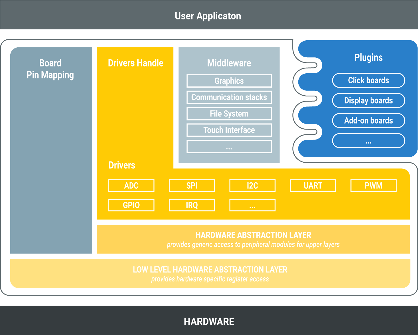
Hardware Abstraction Layer (HAL)
Provides generic access to peripheral modules for upper layers and hides various MCU peripheral instantiation differences, so that the application can be abstracted from the low-level hardware details, enabling highly portable code.
Low Level Hardware Abstraction Layer (HAL)
Provides functions with hardware specific register access details.
Drivers Handle
The Drivers Handle provides API and implementation which allow you to interface with target microcontroller. This layer saves developers time since they no longer need to reinvent commonly used services and do not typically need to interface directly with the hardware. This enables shorter development cycles and rapid prototyping and code re-use on different microcontrollers.
Note
Use this layer to interface with microcontroller peripheral modules to ensure maximum portability, instead of HAL layer.
Middleware
Middleware consists of sets of comprehensive libraries for common application development, such as graphics, communication stacks, file system, etc...
Board Pin Mapping
The Board Pin Mapping comes with the board.h header file with all necessary
pin mapping definitions. It helps to develop portable applications for
mikroBUS socket middleware libraries and other standardized modules witch
comes on board or extension boards.
Plugins
The Plugins libraries are for extension boards, such as Click boards, TFT boards, etc and they are separated from a mikroSDK project.
User Application
The User Application is where users implement logic for their application, using the services provided by the mikroSDK 2.0 framework.
Module context structures
Each module can define context structure for storing its state. The contents of the context structure are used by the module and must not be altered by user. Reading or writing data from a context structure should also be avoided as the data structure is not guaranteed to remain the same between mikroSDK releases. In general, context structures should be treated like black boxes. User of a module is responsible for static instancing, because dynamic memory allocation is not allowed.
The following code snippet shows an example of this:
uart_t uart;

uart.baud = 56000; // Not recommended

uart_set_baud(&uart, 56000); // OK
Using function to set field in context structure ensures encapsulation principles.
Example context structure for a Click driver module is shown below:
typedef struct
{
    digital_out_t out;
    spi_master_t spi;

    int value;
} click_t;
In this example, click_t context structure contains context structure for
digital output (digital_out_t), and context structure for SPI master
driver (spi_master_t). It also can contains other fields for storing
module instance data.
Names of context structures
Naming convention for context structures is <module_name>_t.
Module configuration structures
Each module can provide configuration structure which are used for configuring a module's initial state.
Usually, it contains pin names required for a driver, besides other configuration data.
Example configuration structure is shown here:
typedef struct
{
    pin_name_t out_pin;

    pin_name_t cs_pin;
    pin_name_t sck_pin;
    pin_name_t mosi_pin;
    pin_name_t miso_pin;
} click_cfg_t;
Listed in this example are all pins required by the module. User can use this structure to configure the module to work on desired pins, as shown in the following snippet:
click_t click;
click_cfg_t cfg;

cfg.out_pin = PA11;
cfg.cs_pin = PA12;
cfg.sck_pin = PB8;
cfg.mosi_pin = PB9;
cfg.miso_pin = PB10;

click_init(&click, &cfg);
Board support can simplify this process, and make it more portable with mapping macro, defined by module, as shown in next example:
#include "board.h"

...

click_t click;
click_cfg_t cfg;

CLICK_MAP_MIKROBUS(cfg, MIKROBUS_3);
click_init(&click, &cfg);
Every module should define a function for setting up default values for configuration structures.
Names of configuration structures
Naming convention for configuration structures is <module_name>_cfg_t.
Identifying pins and ports
mikroSDK defines pin_name_t and port_name_t types for identifying pins and
ports on a target MCU. Their size will vary depending on the MCU architecture
and port width.
Each target MCU defines its own pins and ports in hal_target.h header
file, and is responsible for mapping that number to corresponding module
registers and pin masks. Board pin-mapping uses these target pin and port names
to identify pin-outs available on development board.
Another way to directly access a pin in mikroSDK 2.0 is by using Pxy,
where x is a port letter starting from A and y is a pin
number on that port starting from 0. For example, pin PA0 will always be
the first pin on the first port of an MCU. PC5 will be the fifth pin of
the third port, etc...
This applies to all microcontrollers, regardless of
their architecture, port letter / number and width.