SPI Master Driver
SPI Master driver provides functionality for synchronous serial communication interface specification used for short-distance communication, in master mode.
To use this library
Header: #include "drv_spi_master.h"
memake: MikroSDK.Driver
Serial Peripheral Interface (SPI)
SPI devices communicate in full duplex mode using a master-slave architecture with a single master, which controls the peripheral devices (slaves).
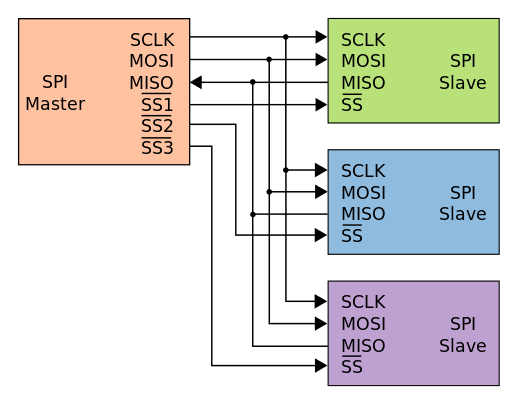
The SPI bus specifies four lines:
| Pin | Desription |
|---|---|
| MISO | The Slave line for sending data to the master. |
| MOSI | The Master line for sending data to the peripherals. |
| SCK | The clock pulses which synchronize data transmission generated by the master. |
| CS | Chip Select (or Slave Select). |
Image below shows a typical SPI bus configuration with single master, and three slave devices.
Initialization
Before calling functions for initiating communication, user must define a SPI Master driver context variable and to call the Open function.
Initialization example of a SPI Master driver instance:
spi_master_t spi;
spi_master_config_t spi_master_cfg;

spi_master_configure_default( &spi_master_cfg );

spi_master_cfg.sck = PA9;
spi_master_cfg.miso = PA10;
spi_master_cfg.mosi = PA11;

spi_master_open( &spi, &spi_master_cfg );
spi_master_set_speed( &spi, 100000 );
The driver tries to find corresponding SPI module for configured pins. If target MCU does not have SPI hardware module connected on selected GPIO pins, or speed is not supported, spi_master_open() returns error.
Example three-byte write:
#define write_count 3

uint8_t wr_buffer[3];

wr_buffer[0] = 0xAA;
wr_buffer[1] = 0xBB;
wr_buffer[2] = 0xCC;

spi_master_select_device( PD0 );    // Chip select pin
spi_master_write( &spi, &wr_buffer, write_count );
spi_master_deselect_device( PD0 );    // Chip select pin
Before and after using SPI functions for write and read, it is required to call
spi_master_select_device() and spi_master_deselect_device() accordingly, in
order to ensure that the CS pin is properly handled.
Example three-byte read:
#define read_count 3

uint8_t rd_buffer[3];

spi_master_select_device( PD0 );    // Chip select pin
spi_master_read( &spi, &rd_buffer, read_count );
spi_master_deselect_device( PD0 );    // Chip select pin
You can use the spi_master_set_default_write_data() function to specify the
dummy data which will be sent when using the spi_master_read() or
spi_master_write_then_read()functions.