


PWM Library
CMO module is available with a number of AVR MCUs. mikroC PRO for AVR provides library which simplifies using PWM HW Module.
 Important :
- AVR MCUs require you to specify the module you want to use. To select the desired PWM, simply change the letter x in the prototype for a number from 1 to 2.
Number of PWM modules per MCU differs from chip to chip. Please, read the appropriate datasheet before utilizing this library.
For the XMEGA family of MCUs change the xn in the routine prototype with C0, C1, D0, D1, E0, E1, F0 or F1 (MCU dependent). - PWM library handles and initializes the PWM module on the given AVR MCU, but it is up to user to set the correct pins as PWM output, this topic will be covered later in this section.
- mikroC PRO for AVR does not support enhanced PWM modules.
Library Routines
- PWMx_Init
- PWMx_Set_Duty
- PWMx_Start
- PWMx_Stop
- PWM1_Enable
- PWMxA_Enable
- PWMxB_Enable
- PWM1_Disable
- PWMxA_Disable
- PWMxB_Disable
- PWMxA_Set_Duty
- PWMxB_Set_Duty
- PWM1_Set_Output
PWMx_Init
| Prototype |
void PWMx_Init(unsigned short wave_mode, unsigned short prescaler, unsigned short inverted, unsigned short duty); |
||||||||||||||||||||||||||||||||||||||||||||||||||||||
|---|---|---|---|---|---|---|---|---|---|---|---|---|---|---|---|---|---|---|---|---|---|---|---|---|---|---|---|---|---|---|---|---|---|---|---|---|---|---|---|---|---|---|---|---|---|---|---|---|---|---|---|---|---|---|---|
| Returns |
Nothing. |
||||||||||||||||||||||||||||||||||||||||||||||||||||||
| Description |
Initializes the PWM module. Parameters :
PWMx_Init must be called before using other functions from PWM Library. |
||||||||||||||||||||||||||||||||||||||||||||||||||||||
| Requires |
You need a CMO on the given MCU (that supports PWM). Before calling this routine you must set the output pin for the PWM (according to the datasheet). |
||||||||||||||||||||||||||||||||||||||||||||||||||||||
| Example |
Initialize PWM module: PWM1_Init(_PWM1_FAST_MODE, _PWM1_PRESCALER_8, _PWM1_NON_INVERTED, 127); |
PWM_xn_Init
| Prototype |
unsigned int PWM_xn_Init(unsigned long int freq_hz, unsigned short wave_mode); |
||||||
|---|---|---|---|---|---|---|---|
| Returns |
Calculated timer period (value written in PER register) for XMEGA family of MCUs. |
||||||
| Description |
Initializes the PWM module. Change the xn in the routine prototype with C0, C1, D0, D1, E0, E1, F0 or F1 (MCU dependent). Parameters :
|
||||||
| Requires |
You need a CMO on the given MCU (that supports PWM). Before calling this routine you must set the output pin for the PWM (according to the datasheet). |
||||||
| Example |
Initialize PWM module: PWM_C0_Init(1000, _PWM_SINGLE_SLOPE); |
PWMx_Set_Duty
| Prototype |
void PWMx_Set_Duty(unsigned short duty); // for ATtiny441/481void PWMx_Set_Duty(unsigned short duty, channel); |
||||||
|---|---|---|---|---|---|---|---|
| Returns |
Nothing. |
||||||
| Description |
Changes PWM duty ratio. Parameter Parameters :
|
||||||
| Requires |
PWM module must to be initialised (PWMx_Init) before using this function. |
||||||
| Example |
PWM1_Set_Duty(192); |
PWM_xn_Set_Duty
| Prototype |
void PWM_xn_Set_Duty(unsigned int duty_ratio, char inverted, char channel); |
||||||||||||||||
|---|---|---|---|---|---|---|---|---|---|---|---|---|---|---|---|---|---|
| Returns |
Nothing. |
||||||||||||||||
| Description |
Changes PWM duty ratio. Parameter Parameters :
|
||||||||||||||||
| Requires |
PWM module must to be initialised (PWM_xn_Init) before using this function. |
||||||||||||||||
| Example |
PWM_C0_Set_Duty(192,_PWM_NON_INVERTED,_CCC_CHANNEL); |
PWMx_Start
| Prototype |
void PWMx_Start(); |
|---|---|
| Returns |
Nothing. |
| Description |
Starts PWM. |
| Requires |
MCU must have CMO module to use this library. PWMx_Init must be called before using this routine. |
| Example |
PWM1_Start(); |
PWM_xn_Start
| Prototype |
void PWM_xn_Start(char channel); |
||||||||||
|---|---|---|---|---|---|---|---|---|---|---|---|
| Returns |
Nothing. |
||||||||||
| Description |
Starts PWM. Parameters :
|
||||||||||
| Requires |
MCU must have CMO module to use this library. PWM module must to be initialised (PWM_xn_Init) before using this function. |
||||||||||
| Example |
PWM_C0_Start(_CCD_CHANNEL); |
PWMx_Stop
| Prototype |
void PWMx_Stop(); |
|---|---|
| Returns |
Nothing. |
| Description |
Stops the PWM. |
| Requires |
MCU must have CMO module to use this library. PWMx_Init and PWMx_Start must be called before |
| Example |
PWM1_Stop(); |
PWM1_Enable
| Prototype |
void PWM1_Enable(unsigned short inverted, channel); |
||||||||||||
|---|---|---|---|---|---|---|---|---|---|---|---|---|---|
| Returns |
Nothing. |
||||||||||||
| Description |
Enables the PWM on desired channel. Parameters :
|
||||||||||||
| Requires |
MCU must have CMO module to use this library. PWMx_Init must be called before
This routine is valid only for ATtiny441/481 MCUs. |
||||||||||||
| Example |
PWM1_Enable(_PWM1_NON_INVERTED, _PWM1_CH_A); |
PWMxA_Enable
| Prototype |
void PWMxA_Enable(unsigned short inverted); |
||||||||||
|---|---|---|---|---|---|---|---|---|---|---|---|
| Returns |
Nothing. |
||||||||||
| Description |
Enables the PWM on channel A. Parameters :
|
||||||||||
| Requires |
MCU must have CMO module to use this library. PWMx_Init must be called before
|
||||||||||
| Example |
PWM1A_Enable(_PWM1_NON_INVERTED); |
PWMxB_Enable
| Prototype |
void PWMxB_Enable(unsigned short inverted, unsigned short modifyTop); |
||||||||||||||||||||
|---|---|---|---|---|---|---|---|---|---|---|---|---|---|---|---|---|---|---|---|---|---|
| Returns |
Nothing. |
||||||||||||||||||||
| Description |
Enables the PWM on channel B. Parameters :
|
||||||||||||||||||||
| Requires |
MCU must have CMO module to use this library. PWMx_Init must be called before
|
||||||||||||||||||||
| Example |
PWM1B_Enable(_PWM1_NON_INVERTED, _PWM1B_TOP_VAL_MAX); |
PWM1_Disable
| Prototype |
void PWM1_Disable(unsigned short channel); |
||||||
|---|---|---|---|---|---|---|---|
| Returns |
Nothing. |
||||||
| Description |
Disables the PWM on desired channel .
Parameters :
|
||||||
| Requires |
MCU must have CMO module to use this library. PWMx_Init must be called before
This routine is valid only for ATtiny441/481 MCUs. |
||||||
| Example |
PWM1_Disable(_PWM1_CH_A); |
PWMxA_Disable
| Prototype |
void PWMxA_Disable(); |
|---|---|
| Returns |
Nothing. |
| Description |
Disables the PWM on channel A.
|
| Requires |
MCU must have CMO module to use this library. PWMx_Init must be called before
|
| Example |
PWM1A_Disable(); |
PWMxB_Disable
| Prototype |
void PWMxB_Disable(); |
|---|---|
| Returns |
Nothing. |
| Description |
Disables the PWM on channel B.
|
| Requires |
MCU must have CMO module to use this library. PWMx_Init must be called before
|
| Example |
PWM1B_Disable(); |
PWMxA_Set_Duty
| Prototype |
void PWMxA_Set_Duty(unsigned short duty); |
|---|---|
| Returns |
Nothing. |
| Description |
Changes PWM duty ratio on channel A. Parameter Parameters :
|
| Requires |
MCU must have CMO module to use this library. PWMx_Init and PWMx_Start must be called before |
| Example |
PWM1A_Set_Duty(192); |
PWMxB_Set_Duty
| Prototype |
void PWMxB_Set_Duty(unsigned short duty); |
|---|---|
| Returns |
Nothing. |
| Description |
Changes PWM duty ratio on channel B. Parameter Parameters :
|
| Requires |
MCU must have CMO module to use this library. PWMx_Init and PWMx_Start must be called before |
| Example |
PWM1B_Set_Duty(192); |
PWM1_Set_Output
| Prototype |
void PWM1_Set_Output(unsigned short chOutputSelectA, chOutputSelectB); |
||||||||||||||||||||||||
|---|---|---|---|---|---|---|---|---|---|---|---|---|---|---|---|---|---|---|---|---|---|---|---|---|---|
| Returns |
Nothing. |
||||||||||||||||||||||||
| Description |
This routine sets TOCCn outputs for channels A and B. Valid only for ATtiny441/481 MCUs. Parameters :
|
||||||||||||||||||||||||
| Requires |
MCU must have CMO module to use this library. PWMx_Init must be called before
|
||||||||||||||||||||||||
| Example |
PWM1_Set_Output(_PWM1_CH_A_OUT_TOCC1, _PWM1_CH_B_OUT_NONE); |
PWM_xn_Stop
| Prototype |
void PWM_xn_Stop(char channel); |
||||||||||
|---|---|---|---|---|---|---|---|---|---|---|---|
| Returns |
Nothing. |
||||||||||
| Description |
Stops the PWM. Parameters :
|
||||||||||
| Requires |
MCU must have CMO module to use this library. PWM_xn_Init and PWM_xn_Start must be called before |
||||||||||
| Example |
PWM_C0_Stop(_CCC_CHANNEL); |
Library Example
The example changes PWM duty ratio on pin PB3 continually. If LED is connected to PB3, you can observe the gradual change of emitted light.

char current_duty;
char current_duty1;

void main(){

  DDB0_bit = 0;                   // Set PORTB pin 0 as input
  DDB1_bit = 0;                   // Set PORTB pin 1 as input

  DDC0_bit = 0;                   // Set PORTC pin 0 as input
  DDC1_bit = 0;                   // Set PORTC pin 1 as input

  current_duty  = 32;             // initial value for current_duty
  current_duty1 = 32;             // initial value for current_duty

  DDB3_bit = 1;                   // Set PORTB pin 3 as output pin for the PWM (according to datasheet)
  DDD7_bit = 1;                   // Set PORTD pin 7 as output pin for the PWM (according to datasheet)

  PWM1_Init(_PWM1_FAST_MODE, _PWM1_PRESCALER_8, _PWM1_NON_INVERTED, current_duty);
  PWM2_Init(_PWM2_FAST_MODE, _PWM2_PRESCALER_8, _PWM2_NON_INVERTED, current_duty1);

  do {
    if (PINB0_bit) {                            // Detect if PORTB pin 0 is pressed
      Delay_ms(40);                             // Small delay to avoid deboucing effect
      current_duty++;                           // Increment duty ratio
      PWM1_Set_Duty(current_duty);               // Set incremented duty
    }
    else
      if (PINB1_bit) {                          // Detect if PORTB pin 1 is pressed
        Delay_ms(40);                           // Small delay to avoid deboucing effect
        current_duty--;                         // Decrement duty ratio
        PWM1_Set_Duty(current_duty);             // Set decremented duty ratio
      }
      else
        if (PINC0_bit) {                        // Detect if PORTC pin 0 is pressed
          Delay_ms(40);                         // Small delay to avoid deboucing effect
          current_duty1++;                      // Increment duty ratio
          PWM2_Set_Duty(current_duty1);         // Set incremented duty
        }
        else
          if (PINC1_bit) {                      // Detect if PORTC pin 1 is pressed
            Delay_ms(40);                       // Small delay to avoid deboucing effect
            current_duty1--;                    // Decrement duty ratio
            PWM2_Set_Duty(current_duty1);       // Set decremented duty ratio
          }

  } while(1);                                   // Endless loop

}
HW Connection
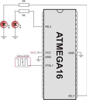
PWM demonstration
What do you think about this topic ? Send us feedback!
Find them on
